Overview
The Aillio Pro Cooling Tray (PCT) is an essential companion to the Bullet R1/R2 roaster. Its motorized paddle and integrated fan pull heat away from freshly roasted beans in minutes, locking in the flavour development you worked so hard to achieve during the roast. The brain behind this mechanism is a small PCB (printed circuit board) that governs motor speed, fan operation, and safety cutoffs.
When the PCB develops a fault — caused by a power surge, moisture ingress, or normal wear — the tray may stop spinning, the fan may fail to start, or the unit may become unresponsive entirely. This guide covers the official Aillio PCB replacement procedure for the Pro Cooling Tray.
Signs You Need a PCB Replacement
- The cooling tray motor does not spin even when powered on.
- The fan runs but the paddle motor is silent.
- The tray is unresponsive and shows no status LED activity.
- Visible burn marks or a burnt smell near the PCB area.
- Error codes in RoasTime pointing to cooling tray communication failure.
What You Will Need
- Replacement PCB for the Aillio Pro Cooling Tray (order from aillio.com or your local distributor).
- JIS or Phillips #1 and #2 screwdrivers.
- Plastic prying tool or spudger.
- Anti-static wrist strap (recommended).
- A clean, well-lit workspace.
Step-by-Step Replacement
- Power off and unplug. Disconnect the Pro Cooling Tray from the Bullet R1/R2 and from the wall outlet. Allow the unit to cool completely.
- Remove the base screws. Flip the tray upside down and remove the screws securing the bottom panel. Keep them in a small container so none are lost.
- Detach the bottom panel. Gently pry the base panel away using a plastic spudger. Avoid metal tools near the PCB to prevent accidental short circuits.
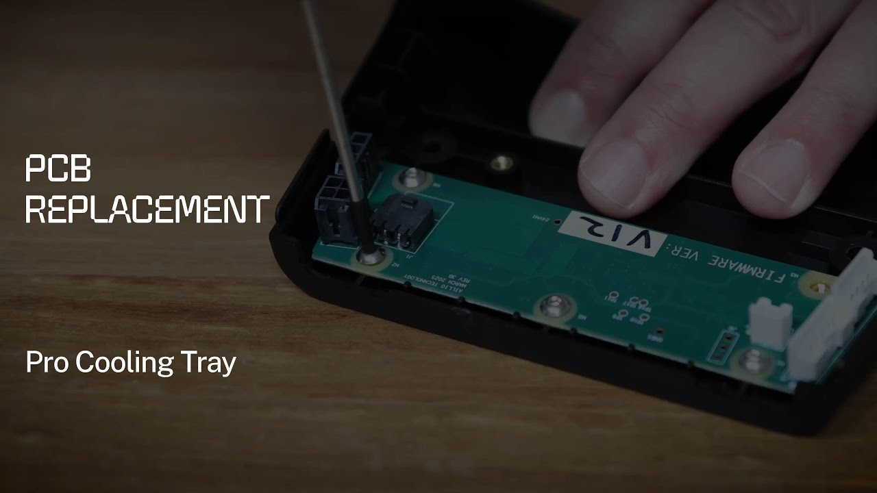
- Locate the PCB. The board sits near the motor housing, connected via ribbon cables and a pair of motor leads.
- Photograph all connectors before disconnecting. Take a clear photo of every cable and its orientation. This is your reassembly reference.
- Disconnect the cables. Unplug the ribbon connectors and motor leads carefully. Most use ZIF (zero insertion force) locks — lift the locking tab before pulling.
- Remove the old PCB. Unscrew the PCB mounting screws and lift the board clear of the chassis.
- Install the replacement PCB. Position the new board, secure the mounting screws (do not overtighten), and reconnect all cables in the same orientation as your reference photo.
- Reassemble. Reattach the base panel and replace all screws.
- Test before full reassembly. Connect the tray to the Bullet, power on, and verify the paddle spins and the fan runs. Confirm RoasTime shows no cooling tray errors.
Tips for a Successful Repair
Always use the genuine Aillio replacement PCB. Third-party boards may not match the firmware revision expected by RoasTime and can introduce new faults. If your unit is still under warranty, contact Aillio Support before opening the tray — self-repair may void coverage.
Need More Help?
This guide accompanies the official Aillio technical support video. For issues beyond a straightforward PCB swap — such as motor damage, structural cracks, or firmware errors — reach out directly to the Aillio Support team at aillio.com/contact-us. Comments on the YouTube video are disabled by design; the support portal is the fastest path to a resolution.